
 Алгебра
 Английский
 Биология
 География
 Геометрия
 История
 Русский
 Обществознание
 Физика
 Химия
Химия Информатика
 Литература
 Математика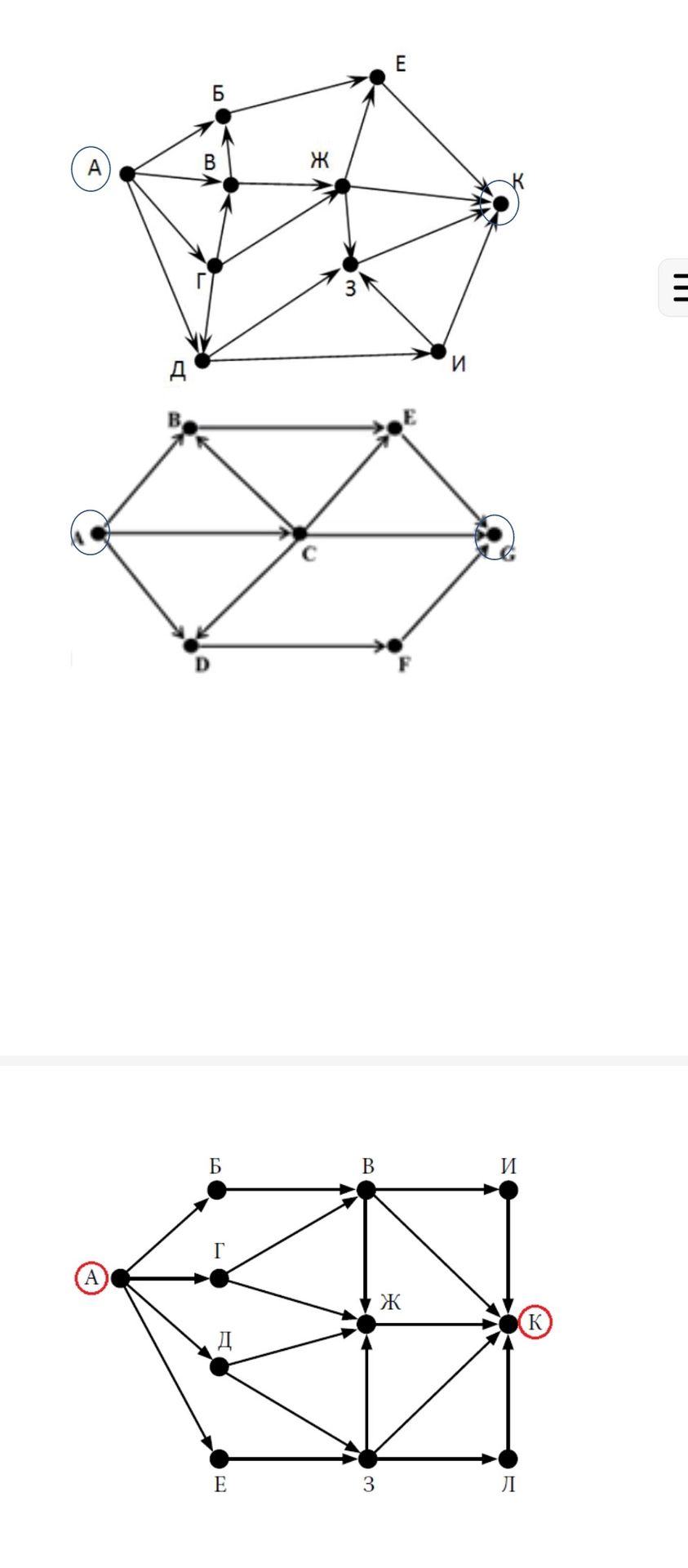
Ответ:
Analysis of Directed Graphs
The image displays three directed graphs, each representing a network of nodes (points) and directed edges (arrows) connecting them. The nodes are labeled with Cyrillic letters and numbers. We will analyze each graph separately.
Graph 1:
This graph has nodes labeled A, Б, В, Г, Д, Е, Ж, З, И, and K. It appears to represent a network with a starting point or source (likely A) and a destination or sink (likely K), indicated by circles around these nodes. Arrows show the direction of flow or connection between nodes.
- Nodes: A, Б, В, Г, Д, Е, Ж, З, И, K
- Edges (Direction): A→Б, A→Г, A→Д, Б→В, Б→Е, В→Ж, Г→В, Г→Д, Д→З, Е→Ж, Е→K, Ж→З, Ж→K, З→И, З→K, И→K
- Highlighted Nodes: A (possibly start), K (possibly end).
Graph 2:
This graph has a hexagonal structure with an additional central node C. Nodes are labeled A, B, C, D, E, F, and G. The edges indicate a flow or relationship between these points.
- Nodes: A, B, C, D, E, F, G
- Edges (Direction): A→B, A→C, A→D, B→C, B→E, C→D, C→E, C→F, D→F, E→G, F→G
- Highlighted Nodes: A (possibly start), G (possibly end).
Graph 3:
This graph is similar in structure to the first graph but uses slightly different labels for some nodes and includes an additional node Л. Nodes are labeled A, Б, В, Г, Д, Е, Ж, K, И, and Л. Node A is highlighted in red and node K is highlighted in a circle.
- Nodes: A, Б, В, Г, Д, Е, Ж, K, И, Л
- Edges (Direction): A→Б, A→Г, A→Д, A→E, Б→В, В→Ж, В→K, Г→Ж, Д→Ж, Д→3, E→3, Ж→K, Ж→Л, 3→K, 3→Л, И→K
- Highlighted Nodes: A (red circle, likely start), K (circled, likely end).
Summary: These directed graphs represent networks with defined pathways and potential starting/ending points. They could be used to model flows, routes, dependencies, or states in various systems.
