
 Алгебра
 Английский
 Биология
 География
 Геометрия
 История
 Русский
 Обществознание
 Физика
 Химия
Химия Информатика
 Литература
 Математика
Вопрос:
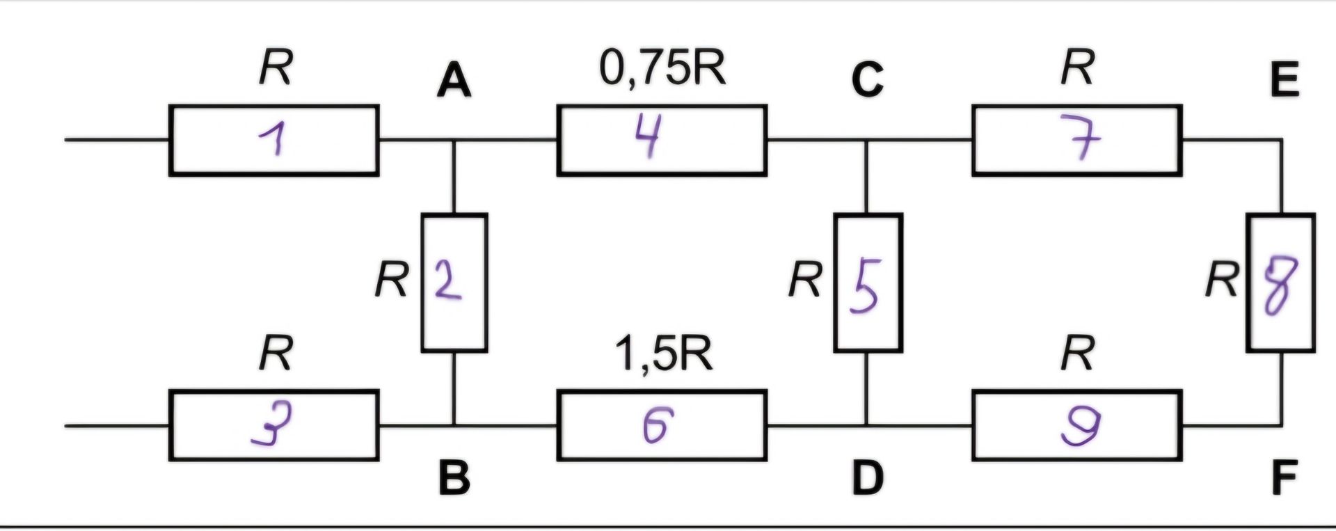
Analyze the provided circuit diagram and identify the components and their configurations.
Ответ:
Circuit Analysis
The provided image displays an electrical circuit diagram containing nine resistors, labeled from 1 to 9. The resistors are arranged in a combination of series and parallel configurations, connected at various nodes labeled A, B, C, D, E, and F. The input and output connections are shown on the left and right sides, respectively.
Components and their resistances:
- Resistor 1: R
- Resistor 2: R
- Resistor 3: R
- Resistor 4: 0.75R
- Resistor 5: R
- Resistor 6: 1.5R
- Resistor 7: R
- Resistor 8: R
- Resistor 9: R
Connections:
- Resistors 1 and 4 are in series, connected between the input line and node A.
- Resistor 2 is connected in parallel between node A and node B.
- Resistors 3 and 6 are in series, connected between the input line and node B.
- Resistors 4 and 7 are in series, connected between node A and node E.
- Resistor 5 is connected in parallel between node C and node D.
- Resistors 6 and 9 are in series, connected between node B and node F.
- Resistors 7 and 8 are in series, connected between node E and node F.
- Resistors 8 and 9 are in series, connected between node F and the output line.
Configuration Summary: The circuit forms a complex network with multiple parallel branches and series elements within those branches. For example, one path from the input to node A involves R1. From A, current can go through R2 to B, or through R4 to C. Similarly, the bottom path to B involves R3 and R6.
