
 Алгебра
 Английский
 Биология
 География
 Геометрия
 История
 Русский
 Обществознание
 Физика
 Химия
Химия Информатика
 Литература
 Математика
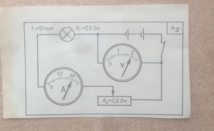
Analyze the provided electrical circuit diagram.
Ответ:
Analysis of the Electrical Circuit Diagram:
The diagram shows a simple electrical circuit containing the following components:
- A power source (battery symbol).
- A switch.
- A light bulb (represented by a circle with an 'X' inside).
- Two resistors labeled R₁ and R₂.
- An ammeter (labeled 'A') to measure current.
- A voltmeter (labeled 'V') to measure voltage.
The following values are indicated:
- Time: \( t = 10 \text{ мин} \) (10 minutes)
- Resistor R₁: \( R₁ = 3.0 \text{ Ом} \) (3.0 Ohms)
- Resistor R₂: \( R₂ = 2.0 \text{ Ом} \) (2.0 Ohms)
The ammeter shows a reading between 0 and 0.2 A, with the needle pointing slightly past 0.2 A, approximately around 0.22 A. The voltmeter shows a reading between 0 and 2 V, with the needle pointing slightly past 1 V, approximately around 1.2 V.
The circuit appears to be a series or parallel combination, but the exact configuration for R2 and the meters relative to R1 and the bulb needs further interpretation based on standard circuit drawing conventions. Assuming R1 is in series with the bulb, and R2 is in parallel with the voltmeter, and the ammeter measures the total current. However, without a clear diagram of the connections for R2 and the meters, a definitive analysis of the circuit's configuration (series, parallel, or mixed) and the relationships between the components is limited. The '4x' in the upper right corner might indicate a multiplication factor or a problem number.
