
 Алгебра
 Английский
 Биология
 География
 Геометрия
 История
 Русский
 Обществознание
 Физика
 Химия
Химия Информатика
 Литература
 Математика
Вопрос:
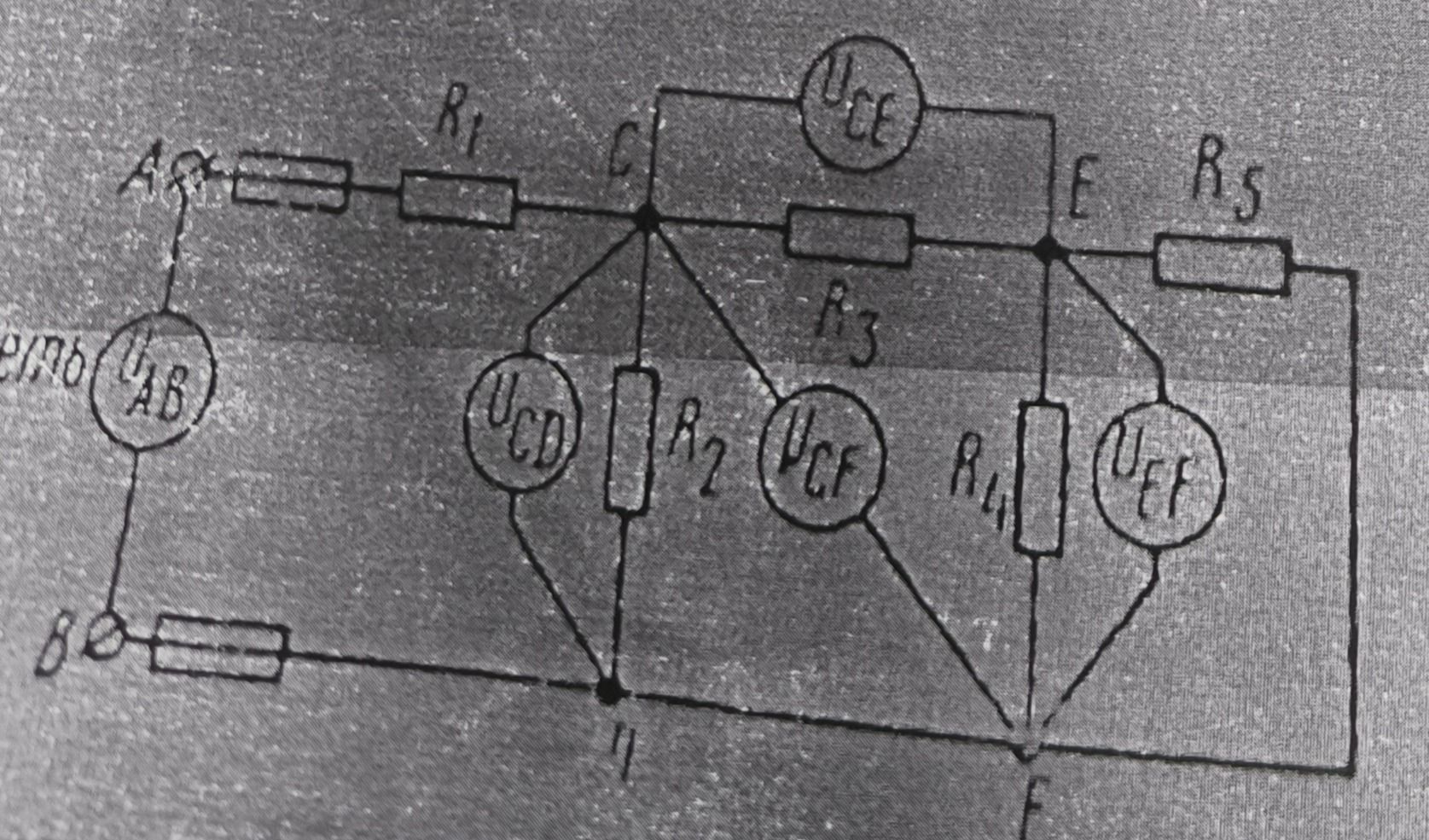
Complete the circuit diagram by identifying the components and their functions.
Ответ:
Electrical Circuit Analysis
The image displays an electrical circuit diagram containing resistors, voltage meters, and connection points labeled with letters. The components are:
- Resistors: Labeled as R1, R2, R3, R4, and R5. These components impede the flow of electric current.
- Voltage Meters: Labeled as UAB, UCE, UCD, UCF, and UEF. These instruments are used to measure the potential difference (voltage) between two points in the circuit. Each meter is connected in parallel across the points it is measuring.
- Connection Points: Labeled as A, B, C, D, E, and F. These represent nodes where different circuit elements are connected. Point 'η' is also shown as a node.
The diagram illustrates a complex network of interconnected components, likely intended for analyzing current and voltage distribution within the circuit under various conditions.
Conclusion: The diagram represents an electrical circuit with resistors and voltmeters, used for measuring voltage drops across different segments of the network.
